
Liquid hydrocarbon flow
Strouhal number at a constant Reynolds number Re = 10+5
Kral meter
Configuration 2: no flow conditioner is placed upstream of the turbine meter as explained in Section 2.2 on page 7 of the CCM.FF-K2 Final Report
Degrees of equivalence: offset Di and expanded uncertainty at a 95 % level of confidence

Liquid hydrocarbon flow
Strouhal number at a constant Reynolds number Re = 10+5
Turbine meter
Configuration 1: a flow conditioner is placed upstream of the turbine meter as explained in Section 2.2 on page 7 of the CCM.FF-K2 Final Report
Degrees of equivalence: offset Di and expanded uncertainty at a 95 % level of confidence

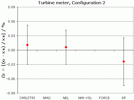
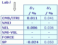
Liquid hydrocarbon flow
Strouhal number at a constant Reynolds number Re = 10+5
Turbine meter
Configuration 2: no flow conditioner is placed upstream of the turbine meter as explained in Section 2.2 on page 7 of the CCM.FF-K2 Final Report
Degrees of equivalence: offset Di and expanded uncertainty at a 95 % level of confidence

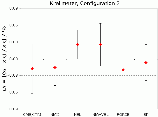
Liquid hydrocarbon flow
Strouhal number at a constant Reynolds number Re = 10+5
Kral meter
Configuration 2: no flow conditioner is placed upstream of the turbine meter as explained in Section 2.2 on page 7 of the CCM.FF-K2 Final Report
| Lab i | Di | Ui |
| / % | / % | |
| CMS/ITRI | -0.018 | 0.044 |
| NMIJ | -0.016 | 0.032 |
| NEL | 0.025 | 0.026 |
| NMi-VSL | 0.025 | 0.038 |
| FORCE | -0.020 | 0.032 |
| SP | -0.007 | 0.032 |
Results are presented under A4 printable format in Summary Results (.PDF file).
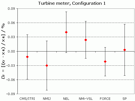
Liquid hydrocarbon flow
Strouhal number at a constant Reynolds number Re = 10+5
Turbine meter
Configuration 1: a flow conditioner is placed upstream of the turbine meter as explained in Section 2.2 on page 7 of the CCM.FF-K2 Final Report
| Lab i | Di | Ui |
| / % | / % | |
| CMS/ITRI | -0.012 | 0.047 |
| NMIJ | -0.030 | 0.052 |
| NEL | 0.040 | 0.043 |
| NMi-VSL | 0.024 | 0.039 |
| FORCE | -0.022 | 0.030 |
| SP | 0.003 | 0.054 |
Results are presented under A4 printable format in Summary Results (.PDF file).
Liquid hydrocarbon flow
Strouhal number at a constant Reynolds number Re = 10+5
Turbine meter
Configuration 2: no flow conditioner is placed upstream of the turbine meter as explained in Section 2.2 on page 7 of the CCM.FF-K2 Final Report

Results are presented under A4 printable format in Summary Results (.PDF file).
| Metrology area, Sub-field | Mass and related quantities, Fluid Flow |
| Description | Liquid hydrocarbon flow |
| Time of measurements | 2005 - 2007 |
| Status | Approved for equivalence |
| Final Reports of the comparisons | |
| Measurand | Strouhal number (corrected for viscosity) at a constant Reynolds number Re = 10+5 |
| Parameters | Flow: 5 l/s to 30 l/s |
| Transfer device | Turbine and Kral meters, tested in two different configurations (Configuration 1: a flow conditioner is placed upstream of the turbine meter; Configuration 2: the flow conditioner is removed) |
| Comparison type | Key Comparison |
| Consultative Committee | CCM (Consultative Committee for Mass and Related Quantities) |
| Conducted by | CCM (Consultative Committee for Mass and Related Quantities) |
| Comments | Results published on 27 November 2008 APMP.M.FF-K2.a results are linked to those of CCM.FF-K2. Liquid hydrocarbon flow Measurements are taken with two meters, designated as "Kral meter" and "Turbine meter", and in two different configurations (Configuration 1: a flow conditioner is placed upstream of the turbine meter; Configuration 2: the flow conditioner is removed), as explained in Section 2.2 on page 7 of the Final Report.
|
| Pilot institute |
NEL
National Engineering Laboratory, now TUVNEL United Kingdom |
| Contact person | R. Paton +44 (0) 1355 272 965 |
| Pilot laboratory | |
|---|---|
| NEL |
National Engineering Laboratory, now TUVNEL, United Kingdom, EURAMET |
| CMS/ITRI |
Industrial Technology Research Institute/Center for Measurement Standards, Chinese Taipei, APMP |
| FORCE |
FORCE Technology, Denmark, EURAMET |
| NMIJ AIST |
National Metrology Institute of Japan, Japan, APMP |
| NMi-VSL |
Nederlands Meetinstituut - Van Swinden Laboratorium (became VSL in 2009), Netherlands, EURAMET |
| SP |
Technical Research Institute of Sweden from 2017 Research Institutes of Sweden AB, Sweden, EURAMET |
This page proposes print-out on A4 paper (portrait) of the comparison details (best printed out using a black and white printer).
Please, select items to be printed out, then click on "OK" :
Liquid hydrocarbon flow
Strouhal number at a constant Reynolds number Re = 10+5
Kral meter
Configuration 2: no flow conditioner is placed upstream of the turbine meter as explained in Section 2.2 on page 7 of the CCM.FF-K2 Final Report
|
The key comparison reference value xR is calculated as the weighted mean of the participants' results, as explained in Section 5.4 on page 17 of the CCM.FF-K2 Final Report. Its expanded uncertainty is UR. xR = 7.9496, UR = 0.015 % |
| The degree of equivalence of laboratory i with respect to the key comparison reference value is given by a pair of terms, both expressed in relative terms: Di = (xi - xR)/xR and its expanded uncertainty Ui = (ULab i2 - UR2)1/2. |
| The degree of equivalence between two laboratories i and j is given by two terms both expressed in relative terms : Dij = (Di - Dj) and associated expanded uncertainty Uij = (ULab i2 + ULab j2)1/2. |
Liquid hydrocarbon flow
Strouhal number at a constant Reynolds number Re = 10+5
Turbine meter
Configuration 1: a flow conditioner is placed upstream of the turbine meter as explained in Section 2.2 on page 7 of the CCM.FF-K2 Final Report
|
The key comparison reference value xR is calculated as the weighted mean of the participants' results, as explained in Section 5.4 on page 17 of the CCM.FF-K2 Final Report. Its expanded uncertainty is UR. xR = 7.1878, UR = 0.019 % |
| The degree of equivalence of laboratory i with respect to the key comparison reference value is given by a pair of terms, both expressed in relative terms: Di = (xi - xR)/xR and its expanded uncertainty Ui = (ULab i2 - UR2)1/2. |
| The degree of equivalence between two laboratories i and j is given by two terms both expressed in relative terms : Dij = (Di - Dj) and associated expanded uncertainty Uij = (ULab i2 + ULab j2)1/2. |
Liquid hydrocarbon flow
Strouhal number at a constant Reynolds number Re = 10+5
Turbine meter
Configuration 2: no flow conditioner is placed upstream of the turbine meter as explained in Section 2.2 on page 7 of the CCM.FF-K2 Final Report
|
The key comparison reference value xR is calculated as the weighted mean of the participants' results, as explained in Section 5.4 on page 17 of the CCM.FF-K2 Final Report. Its expanded uncertainty is UR. xR = 7.1715, UR = 0.030 % |
| The degree of equivalence of laboratory i with respect to the key comparison reference value is given by a pair of terms, both expressed in relative terms: Di = (xi - xR)/xR and its expanded uncertainty Ui = (ULab i2 - UR2)1/2. |
| Pair-wise degrees of equivalence are not computed for the Turbine meter in Configuration 2. |
Liquid hydrocarbon flow
Kral meter
Configuration 2: no flow conditioner is placed upstream of the turbine meter as explained in Section 2.2 on page 7 of the CCM.FF-K2 Final Report
xi : measurement result reported by laboratory i: Strouhal number at a constant Reynolds number Re = 10+5
ULab i : expanded uncertainty of xi
| Lab i | xi | ULab i / % | Date of measurement |
| CMS/ITRI |
7.9482 |
0.045 | March 2006 |
| NMIJ | 7.9484 | 0.03 | April 2006 |
| NEL | 7.9516 | 0.025 | October 2006 |
| NMi-VSL | 7.9516 | 0.04 | February 2007 |
| FORCE | 7.9480 | 0.035 | February 2007 |
| SP |
7.9491 |
0.028 |
March 2007 |
Liquid hydrocarbon flow
Turbine meter
Configuration 1: a flow conditioner is placed upstream of the turbine meter as explained in Section 2.2 on page 7 of the CCM.FF-K2 Final Report
xi : measurement result reported by laboratory i: Strouhal number at a constant Reynolds number Re = 10+5
ULab i : expanded uncertainty of xi
| Lab i | xi | ULab i / % | Date of measurement |
| CMS/ITRI |
7.1870 |
0.045 | March 2006 |
| NMIJ | 7.1857 | 0.03 | April 2006 |
| NEL | 7.1907 | 0.025 | October 2006 |
| NMi-VSL | 7.1895 | 0.04 | February 2007 |
| FORCE | 7.1863 | 0.035 | February 2007 |
| SP |
7.1880 |
0.028 |
March 2007 |
Liquid hydrocarbon flow
Turbine meter
Configuration 2: no flow conditioner is placed upstream of the turbine meter as explained in Section 2.2 on page 7 of the CCM.FF-K2 Final Report
xi : measurement result reported by laboratory i: Strouhal number at a constant Reynolds number Re = 10+5
ULab i : expanded uncertainty of xi
| Lab i | xi | ULab i / % | Date of measurement |
| CMS/ITRI |
7.1723 |
0.045 | March 2006 |
| NMIJ | - | - | - |
| NEL | 7.1719 | 0.025 | October 2006 |
| NMi-VSL | - | - | - |
| FORCE | - | - | - |
| SP |
7.1698 |
0.028 |
March 2007 |